







An active GPS antenna contains a low-noise amplifier (LNA), usually with filtering, and takes DC power through its coaxial cable. A passive GPS antenna has no amplifier: it is the radiating element, sometimes with passive matching or filtering. Neither type is better in general. When the antenna sits right next to the receiver, a passive antenna is often enough. When a cable run separates them, such as a roof antenna feeding a receiver inside a vehicle, an active antenna is usually the right choice. Enough low-noise gain before the cable makes the cable's contribution to the system noise figure small, provided the remaining gain and signal level suit the receiver.
Why GNSS signals need careful handling
GPS L1 signals at 1575.42 MHz reach the antenna at roughly −130 dBm under open sky. Thermal noise in the roughly 2 MHz bandwidth of the L1 C/A signal is about −111 dBm, so the satellite signal is around 20 dB below the noise. The receiver recovers it by correlating with the known spreading code. Signal quality is measured as the carrier-to-noise density ratio, C/N0, in dB-Hz. Loss in front of the first amplifier, and noise added by the receiving chain, lower C/N0 for every satellite.
Passive GPS antennas
A passive GPS antenna is typically a ceramic patch, a helix, a chip or a printed element, matched to 50 Ω and connected to the receiver through a short trace or cable. Nothing sits between the element and the receiver input, so any loss in the trace, cable, connectors or matching network adds directly to the system noise figure.
Passive antennas suit products in which the antenna is close to the GNSS receiver: trackers, wearables, handheld devices and designs with the antenna on the same board as the module. Many GNSS receivers and modules include an LNA and a SAW filter at their RF input for this reason. A passive antenna draws no power and has no active parts. More detail: passive GPS antennas for IoT and automotive applications.
Active GPS antennas
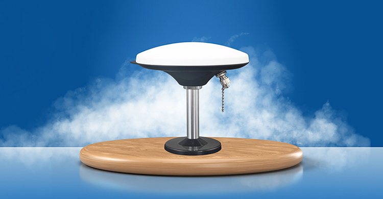
An active antenna places an LNA, normally with one or more band-pass filters, directly behind the radiating element. The receiver supplies DC bias on the centre conductor of the coaxial cable, commonly somewhere in the 3–5 V range, and the antenna draws from a few milliamps to a few tens of milliamps; check both datasheets. Antenna LNA gains are commonly between about 15 and 30 dB, and higher-gain versions exist for long cable runs.
The LNA does not remove noise. It amplifies the satellite signal and the noise together, and adds a little noise of its own. What it does is set the system noise figure at the antenna: once the signal has been amplified, the loss of the cable that follows has very little effect.
A simplified comparison shows the size of the effect. The values are assumptions for illustration: 5 dB of cable and connector loss at 1575 MHz, a receiver noise figure of 2 dB, and an antenna LNA with 28 dB gain and a 1.5 dB noise figure.
| Set-up | Signal chain | System noise figure |
|---|---|---|
| Passive antenna, 5 dB cable | Antenna → cable → receiver | ≈ 7.0 dB |
| Active antenna, 5 dB cable | Antenna → LNA → cable → receiver | ≈ 1.5 dB |
Under these assumptions the passive set-up gives roughly 5.5 dB lower C/N0 on every satellite than the active one. The calculation uses the Friis noise formula with the standard 290 K reference and ignores filter loss ahead of the LNA and the antenna's own noise temperature, but the conclusion holds: put the gain before the loss. For long installations, see GNSS timing antenna signal chain and installation.
Matching an active antenna to the receiver
- Gain range. Check the net LNA gain, after cable and connector losses, against the receiver's recommended range. Too little gain leaves cable loss uncompensated. Too much can overload the receiver front end, especially near strong transmitters. Datasheets sometimes mix up LNA gain and the gain of the radiating element; judge the element's gain, efficiency and polarization separately, because LNA gain cannot make up for a poor element.
- Bias supply. Confirm that the receiver, or a separate bias tee, provides the voltage and current the antenna needs, and whether the supply has current limiting. Many receivers use the antenna current to report an open or shorted antenna.
- DC on the cable. Splitters, test equipment and some passive antennas are not designed to receive DC. Use a DC block or a DC-passing splitter as required, and check whether a passive antenna presents a DC short before connecting it to a port that supplies bias.
- Filtering. Strong nearby signals, such as cellular transmitters in the same shark-fin housing or L-band satellite terminals, can drive an LNA into compression. Antennas intended for these environments use stronger filtering, at the cost of a little extra loss when the filter sits in front of the LNA.
- Frequency bands. Make sure the element, filters and LNA all cover the signals you need, for example GPS L1, Galileo E1, BeiDou B1 and GLONASS G1 between about 1559 and 1606 MHz, and L5/E5a at 1176.45 MHz for dual-band receivers. See multi-band GNSS antenna selection and vehicle installation.
What neither type can fix
- Sky view. Neither type can restore a signal that is completely blocked, for example by a metal roof. Metallised window films and dense surroundings weaken signals and add multipath. Placement comes first, so check reception in the intended installation.
- Polarization and ground plane. GNSS signals are right-hand circularly polarized (RHCP). Patch antennas are designed for RHCP. A linearly polarized chip or PCB antenna gives up about 3 dB and is more sensitive to reflected signals (multipath). Patch gain figures in datasheets are measured on a stated ground plane, and a smaller ground plane in the finished product changes the result.
- Time to first fix. An active antenna does not guarantee a faster fix. Time to first fix depends on whether the receiver holds current almanac, ephemeris and time information or assistance data, on the sky view and on signal strength. Better C/N0 helps under weak-signal conditions, but it is one factor among several.
Quick guide: active or passive?
| Situation | Usual choice | Reason |
|---|---|---|
| Antenna on the same board as the GNSS module, or a few centimetres from it | Passive | Little loss before the receiver input, where the module's own LNA does the job |
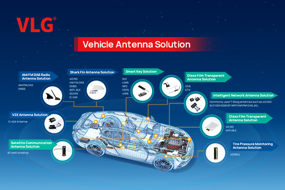
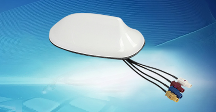
| Roof or shark-fin antenna feeding a receiver inside a vehicle | Active | Several metres of coaxial cable between antenna and receiver |
| External puck antenna for a tracker, telematics box or industrial device | Active | Leads are usually one to several metres long |
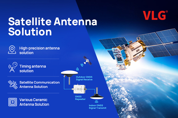
| Timing receiver with a long rooftop cable run | Active, with enough gain for the cable, or with an in-line amplifier | Cable loss over tens of metres |
| Battery-critical device with a short antenna path | Passive | No antenna bias current |
Related reading
- What is a GPS antenna? Types and applications
- Vehicle GPS antennas
- GPS signal enhancement amplifiers
Compare GNSS antenna options with VLG
Deciding between an active and a passive GNSS antenna for a vehicle, tracker or timing product? Contact VLG with the receiver model, cable length and mounting position, and we can help you compare the options.
 +86 186 8871 1070


