







A multi-band GNSS antenna must match the receiver's supported signals and the vehicle installation. For an L1/L2/L5 project, assess band coverage, the active RF signal path and the mounting location together. A higher headline gain does not replace these checks.
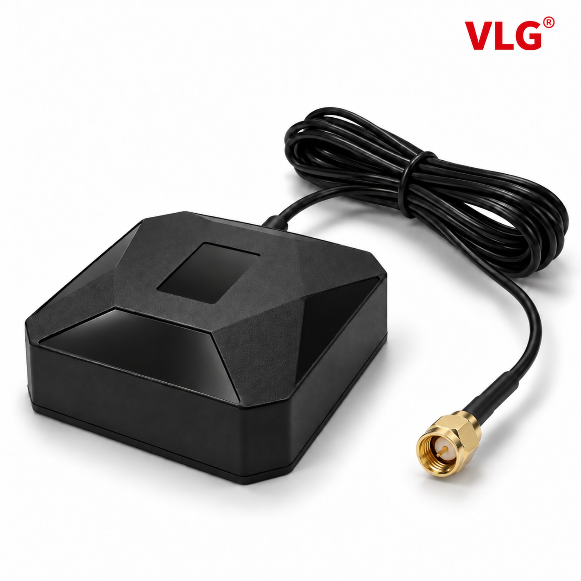
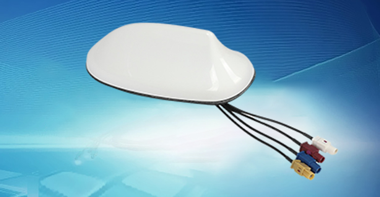
VLG V2455-001-A-01 external GNSS antenna, shown from the existing product image set. Confirm the final configuration and approved electrical data for your receiver and installation.
V2455-001-A-01 configuration for project review
The VLG V2455-001-A-01 is an external L1/L2/L5 GNSS antenna. Its specified efficiency is at least 70%, and its LNA gain is 32 ± 2 dB. The LNA value refers to amplifier gain, not passive antenna gain.
The specified protection rating is IP67. Screw mounting and adhesive mounting are available configuration options; confirm the selected attachment and installation details when ordering.
Match GNSS signals to the receiver
Start with the receiver model and enabled signals. Multi-band and multi-constellation describe different capabilities: frequency coverage and support for satellite systems both need checking. Do not assume that every antenna described as “GNSS” covers every signal used by a receiver.
For an L1/L2/L5 antenna, review the performance data across the required bands rather than relying on a single peak value. Relevant information may include impedance matching, passive gain, radiation patterns, polarization and axial ratio, depending on the application.
Separate passive antenna gain from LNA gain
An active GNSS antenna includes a low-noise amplifier. The radiating element and the amplifier perform different jobs, so their gain figures should be identified separately. LNA gain does not describe the antenna's radiation efficiency.
Review the receiver's active-antenna requirements, permitted RF input conditions and bias supply. Confirm supply voltage, available current, cable loss and any filtering in the signal path. If bias is supplied through the coaxial cable, check the complete connection arrangement before applying power.
Plan a mounting position with a clear sky view
The mounting position determines which satellite signals can reach the antenna and how nearby objects affect reception. Evaluate roof obstructions, roof racks, large adjacent structures and electronic equipment. The u-blox GNSS antenna application note recommends an unobstructed sky view and careful separation from interference sources.
For a patch-based antenna, follow the specified orientation and mounting-surface requirements. The u-blox guidance describes keeping the patch plane parallel to the horizon. Confirm the selected assembly's own ground-plane requirements rather than assuming that all housings use the vehicle roof in the same way.
An antenna placed under a windshield should be tested with that exact glass and location. Coatings and surrounding vehicle structure can affect reception. Do not assume that a convenient dashboard position will perform like a suitable roof installation.
Specify the cable, connector and mounting method
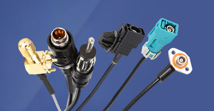
Agree the cable type and length, mating connector, bend constraints and strain relief. Check the route through the vehicle before ordering samples. Avoid changing cable length or adding adapters after validation without reviewing the RF path.
Mounting and environmental requirements should refer to the actual assembly. Confirm the approved attachment method and sealing arrangement for the project. Keep mechanical drawings, installation instructions and the final test configuration together.
Validate reception on the intended vehicle
Compare candidate antenna positions using the same receiver, firmware, enabled signals and test route. Record signal quality by band, satellite availability, acquisition behavior and positioning stability where relevant.
For an RTK application, include the correction source, receiver configuration and solution status in the test record. Positioning accuracy is a system result. An antenna alone cannot guarantee centimeter-level positioning, lane-level accuracy or uninterrupted operation in a tunnel.
Multi-band GNSS antenna FAQ
Does more LNA gain always improve positioning?
No. The amplifier, cable and receiver need a compatible signal budget. Review the receiver's requirements and the complete RF chain rather than selecting by the largest gain number.
Can an L1-only receiver use L2 and L5 because the antenna covers them?
No. Receiving and processing additional bands requires a receiver that supports those signals. Antenna coverage does not add receiver capabilities.
What information helps VLG recommend a GNSS antenna?
Provide the receiver model, required bands, bias supply, cable and connector needs, mounting drawing and intended vehicle environment. Include positioning and test requirements so the discussion addresses the complete installation.
For timing systems, see our GNSS timing antenna guide. Contact VLG to discuss a vehicle GNSS antenna requirement.
Technical reference: u-blox GNSS antennas application note.
 +86 186 8871 1070


