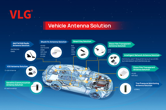
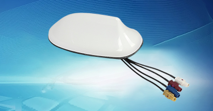
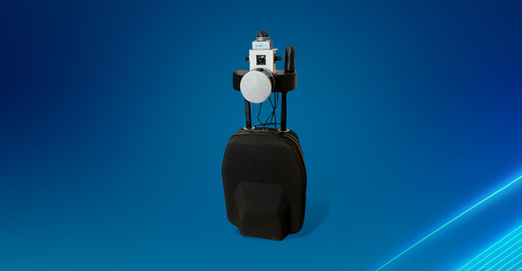
The VLG V2144-005-A-01 V2X antenna assembly brings cellular communication, satellite reception and a dedicated 5.9 GHz path into a combined vehicle installation. It is intended for on-board unit projects in connected transport. The design should be evaluated against the OBU radio architecture, with each RF feed assigned to the correct cellular, GNSS or V2X input.
Key specifications and selection criteria
| Item |
Details |
| Model |
V2144-005-A-01 |
| Cellular ranges |
700–960 / 1710–2690 / 3300–5000 MHz |
| V2X range |
5855–5925 MHz |
| GNSS LNA gain |
30 ± 3 dB |
| GNSS supply / current |
3.0–16 V; 30–50 mA |
| Impedance |
50 Ω |
| Mounting / protection |
Adhesive; IP67 housing |
| Operating temperature |
−40 to +85 °C |
Separate 5G backhaul from the V2X radio path
The cellular section lists 700–960, 1710–2690 and 3300–5000 MHz. The V2X section lists 5855–5925 MHz. These are different RF paths serving different system functions. The antenna assembly does not itself supply a C-V2X modem, vehicle application software or network service.
Confirm the GNSS frequency plan
The design specification describes multi-band GNSS reception. Establish the exact L-band signals required by the receiver and obtain the corresponding frequency plots and feed drawing. Do not infer a complete constellation-and-band matrix from a general high-precision navigation label.
Test coexistence on the assembled OBU
Evaluate GNSS reception during cellular and V2X transmission. Check feed isolation, connector mapping and cable routing, together with interference from the OBU electronics. A combined housing can reduce the number of separate installation locations, but the final RF performance still depends on the vehicle and mounting arrangement.
Specify the installation for the transport project
Document the vehicle location, ground arrangement, cable lengths and required sealing. For a system with several cellular or V2X feeds, verify the actual port count on the released drawing before ordering. Select the antenna version using the radio’s permitted operating configuration for the destination market.
Frequently asked questions
Is a V2X antenna a complete collision-warning system?
No. It is an RF component. The radio, software, vehicle integration and system validation determine the resulting functionality.
Can one cellular cable replace all MIMO inputs?
No. Match the number and function of RF paths to the OBU specification; confirm the assembly’s port drawing.
Explore related vehicle antenna products for your project.
Discuss your antenna project with VLG
Send VLG your required frequency bands, radio or receiver model, available installation space and cable requirements. Include the target application and order quantity so the team can review a suitable antenna configuration.
Request antenna specifications, samples or an OEM quotation.









 Home >
  +86 186 8871 1070


