







An L1/L5 GNSS antenna for agricultural machinery can meet its bench specifications and still deliver disappointing reception after installation on a machine. The cab, mounting bracket, cable route and nearby electronics all become part of the receiving environment. For an engineer, the useful question is which design or installation change could improve the signal reaching the receiver—and how to prove that it helped.
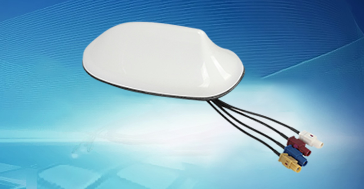
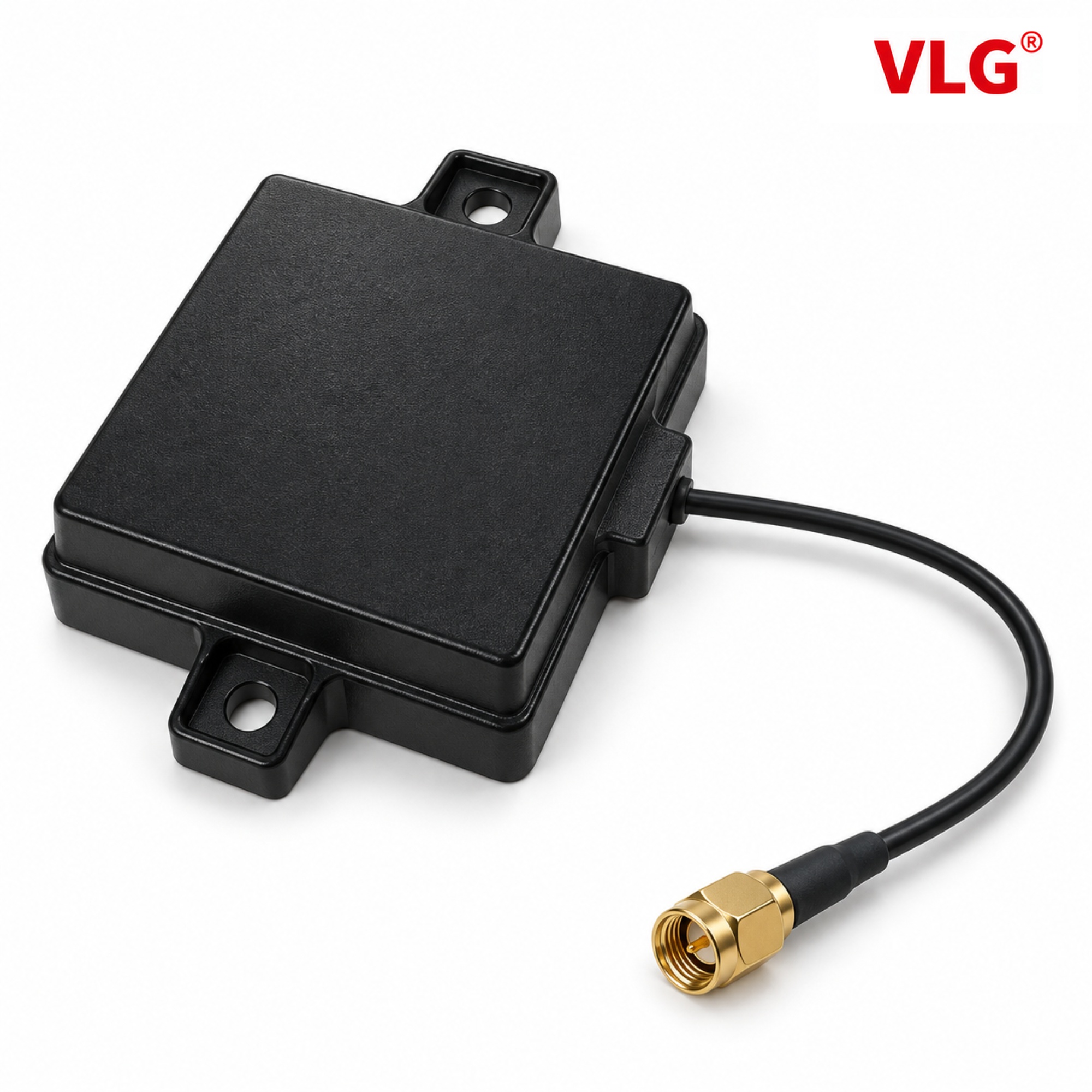
This guide examines those decisions using VLG V2005-017-A-01, an external GNSS antenna with documented L1/L5 support, RHCP polarization and mounting ears. The aim is to connect antenna design with reception and machine-level requirements, while keeping source measurements separate from proposed field tests.
Start with the signal problem, not the highest gain number
A receiver needs usable signals from the right frequencies and directions. A poor result can come from an unsupported signal, blocked sky, reflected paths, installation losses or interference. Each calls for a different investigation.
| Engineering question | Antenna or installation decision | Result to check |
|---|---|---|
| Are the required signals supported? | Match the receiver's signal list to the antenna bands | Observations on each required frequency |
| Is the machine obstructing reception? | Compare antenna position and orientation | Per-signal C/N0, tracking continuity and satellite geometry |
| Does performance change with machine equipment switched on? | Investigate placement and the RF environment | Repeatable changes in receiver observations |
| Is the result consistent after installation? | Control mounting, cable assembly and reference position | Repeatability across assembly and operating states |
The benefit to the equipment manufacturer is a shorter, more focused diagnostic process. It avoids treating every reception problem as a need for more antenna gain.
Why L1/L5 support matters to the receiver design
GPS L1 and L5 are centred at 1575.42 MHz and 1176.45 MHz. A compatible antenna must provide useful behaviour in both frequency regions. Supporting one does not establish the response of the other.
The V2005-017-A-01 supported-band table marks GPS L1 and L5 as supported and GPS L2 as unsupported. A receiver configuration requiring GPS L2 therefore needs a different compatibility assessment. Multiple constellation names should not be interpreted as support for every signal from each constellation.
Dual-frequency observations can help a suitably designed receiver estimate or mitigate first-order ionospheric delay because that contribution varies approximately with 1/f². The antenna enables reception of the required RF signals; the receiver performs the measurement processing. This is a reason to preserve both frequency channels, not an antenna-only accuracy guarantee.
For an RTK system, also ask about phase-centre behaviour. The electrical reference point can vary with frequency and signal direction. Housing dimensions and a gain table cannot establish that variation. The supplied V2005 document does not provide a phase-centre calibration or a completed agricultural field qualification.
What the V2005 measurements tell an engineer
The supplied V2005-017-A-01 datasheet lists these frequency-point results:
| Frequency | VSWR | Efficiency | Gain | Axial ratio |
|---|---|---|---|---|
| 1176 MHz | 1.08 | 55.7% | 2.50 dBi | 0.35 dB |
| 1561 MHz | 1.35 | 59.0% | 2.42 dBi | 0.11 dB |
| 1575 MHz | 1.38 | 54.0% | 2.19 dBi | 0.11 dB |
These are values from the source document, not new measurements. Preserve their labels and units when comparing them with another antenna. Confirm the efficiency and gain conventions, cable configuration, reference plane and mounting conditions. Three reported points do not establish every frequency or viewing angle.
At the 1575 MHz point, VSWR 1.38 gives approximately 2.55% reflected incident test power using |Γ| = (VSWR − 1)/(VSWR + 1) and reflected fraction = |Γ|². That calculation describes impedance mismatch at a real reference impedance. It does not mean the antenna is 97.45% efficient: the separate efficiency entry is 54.0%.
This distinction matters in design work. Better matching may reduce one loss mechanism, while conductor loss, directional response, cable attenuation or interference still limits reception. Check the complete RF path instead of using the VSWR minimum as the sole selection criterion.
How RHCP and axial ratio relate to reflected signals
Direct GNSS satellite signals are RHCP. Reflections can change polarization, so an antenna's directional response to RHCP and LHCP components matters when evaluating multipath.
Axial ratio describes the shape of the polarization ellipse. AR in dB equals 20 log10 of the major-to-minor electric-field amplitude ratio; ideal circular polarization is 0 dB. The V2005 source values describe near-circular polarization at the reported conditions, but axial ratio alone does not identify handedness or quantify installed multipath rejection.
Request angular co-polarized and cross-polarized patterns for the relevant installation. Low-elevation reception and reception near zenith can differ. On machinery, cab structures and operating tilt may change which directions matter. The intended benefit is better control over a potential source of poor measurements; an actual improvement in tracking or positioning must be demonstrated with the receiver.
What the mounting ears solve—and what the bracket must solve
Mounting ears provide defined attachment locations. With a suitable joint and bracket, they can help keep antenna position and orientation repeatable. The mechanical table lists an outer size of 94.15 × 68.2 × 21 mm; use the drawing for the complete envelope and hole arrangement.
The bracket design must establish fasteners, preload, stiffness and retention for the machine's operating conditions. The ears themselves are not evidence of a qualified vibration level. Likewise, changing the mounting surface can change the RF environment: nearby metal and added covers can affect impedance and radiation patterns.
Treat the antenna, support and cable route as one installation. Keep cable strain away from connectors and moving joints, follow the cable's bend requirements, and preserve the agreed receiver reference. The internal radiating-element layout is not disclosed, so a specific internal feed or ceramic structure is not inferred from the housing photograph.
A practical comparison that connects signal quality to guidance
Consider an engineering evaluation of two mounting positions: one near an obstructing cab structure and one with a clearer sky view. This is a proposed test scenario, not a VLG customer case.
Keep the receiver, firmware, antenna assembly, correction arrangement and settings consistent. Record each location and its surrounding structure. Compare per-signal C/N0 on comparable signals and satellite elevations, track continuity, and cycle-slip or solution-state information where available. Account for changing satellite geometry across observation periods.
Then assess the system outcome. Does the receiver maintain the required positioning state? Does the completed machine meet its guidance limits? If reception improves but guidance does not, investigate corrections, receiver configuration, reference offsets and the control system. Better antenna reception and better steering are related engineering objectives, but they are different results.
No supplied before-and-after machine test supports a percentage improvement in availability, a shorter acquisition time or fewer missed crop rows. A useful qualification report would show the controlled installation change, the reception evidence and the machine result together.
Discuss an agricultural GNSS installation with VLG
Provide the receiver model, required signals, proposed mounting drawing, operating orientation, cable and connector requirements, and system acceptance criteria. For V2005-017-A-01, request the current assembly drawing and applicable measurement conditions.
Browse VLG GNSS antennas or contact VLG to review the requirement.
Technical references: u-blox GNSS antenna integration guidance and the GPS L5 interface specification. These provide general technical context; the VLG values above come from the corresponding model's supplied datasheet.
 +86 186 8871 1070


