







An embedded 4G LTE PCB antenna must be selected for the device it will operate inside. For an IoT terminal, the required LTE bands, enclosure space and modem interface should be checked together. This guide covers the practical decisions to make before approving an internal antenna.
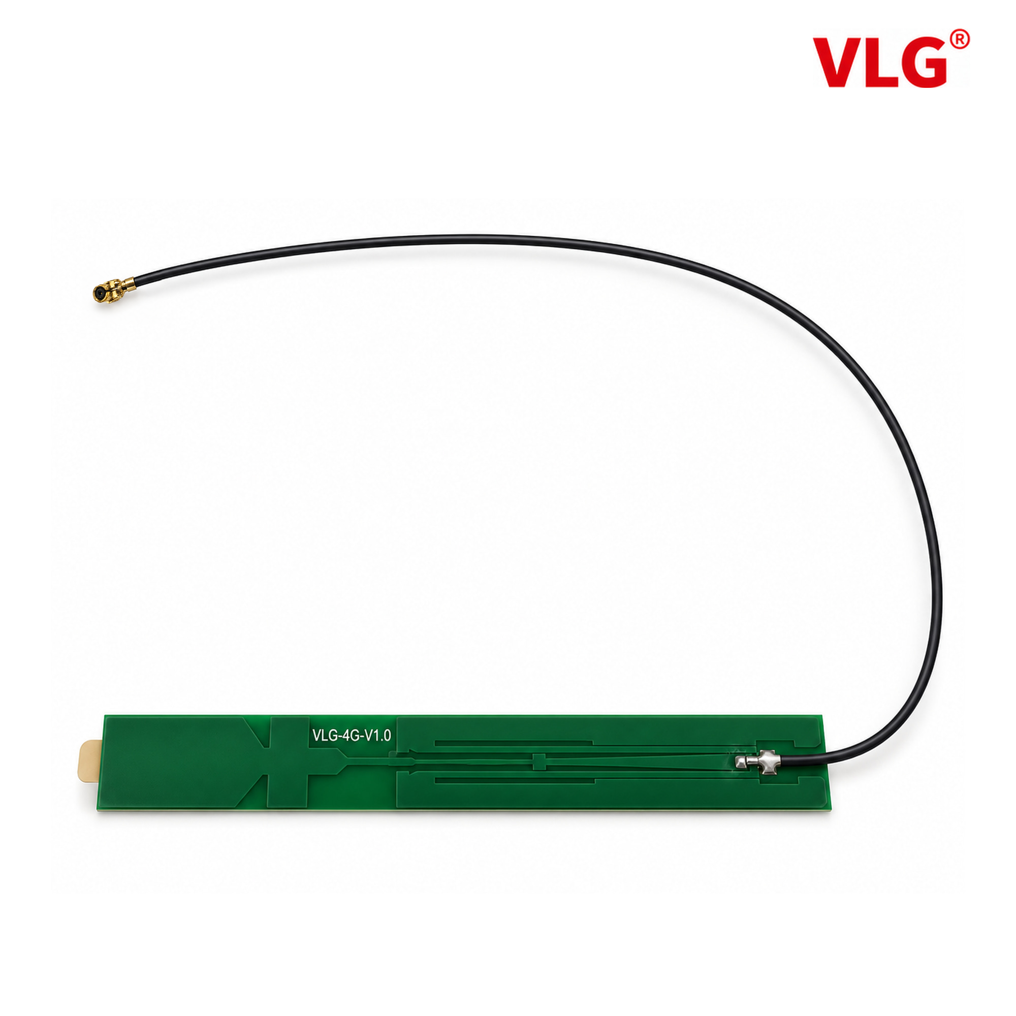
VLG V2282-001-A-01, shown as an example of a separate PCB antenna with a cable feed. Confirm frequency coverage and the connector configuration against the current model documentation.
What is an embedded 4G LTE PCB antenna?
An embedded 4G PCB antenna places the radiating structure on a printed circuit board inside the equipment enclosure. The term may describe a trace designed directly on the main board or a separate rigid PCB antenna connected to the radio module. These are different integration approaches and should not be treated as interchangeable.
A separate antenna board can be positioned inside the enclosure and connected by a suitable feed arrangement, often a coaxial cable. Its internal location can support a clean exterior and avoid an external antenna protrusion. It does not, by itself, give the complete device a waterproof rating.
Choose LTE bands for the modem and target market
List the LTE bands required by the modem, network and destination market before choosing the antenna. “4G antenna” is a product category, not proof that one model covers every LTE band or every operator.
Use the frequency coverage and RF data for the specific antenna model. Review the test setup as well as headline gain or VSWR figures. Do not transfer measured values from a different PCB design, cable assembly or enclosure.
Internal LTE antenna placement and ground-plane requirements
The nearby housing, battery, display, shielding, cables and main-board ground can affect an internal antenna. A non-metallic enclosure does not eliminate the need to evaluate these interactions.
Agree the antenna position, orientation and required clearance early in the mechanical design. Follow the antenna design’s ground-plane and keep-out requirements. Avoid assuming that an antenna can be attached anywhere inside a finished product without retuning or validation.
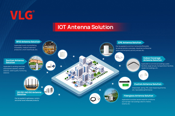
Embedded PCB antennas may be considered for industrial data terminals, connected sensors, cameras and other IoT equipment. Whether a particular model is suitable depends on the available space, radio requirements and final-device test results.
Confirm the cable and connector assembly
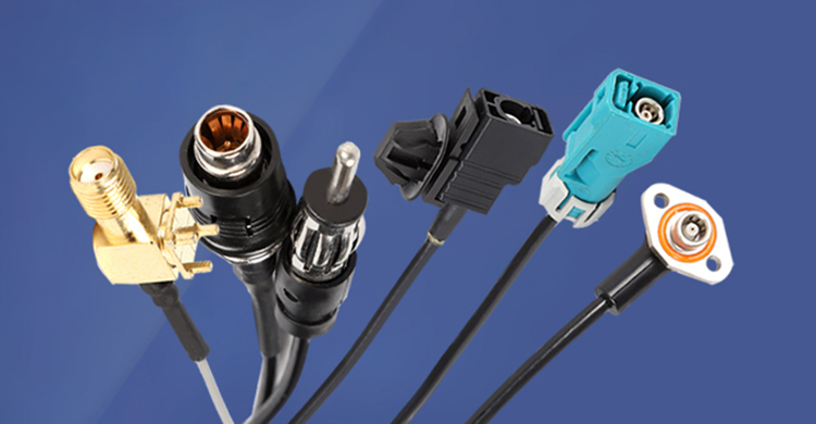
Specify the connector series and mating interface precisely. Small RF connectors that look similar are not necessarily interchangeable. Check the modem-side receptacle, cable length, cable routing and assembly constraints against drawings.
For a separate antenna board, the cable is part of the RF design. Route and secure it consistently with the validated assembly, and review cable loss when changing its length or type.
Validate LTE antenna performance in the finished device
VSWR or return loss helps evaluate impedance matching, but matching alone does not establish radiation efficiency or network performance. Review efficiency, radiation patterns and relevant device-level radio tests as the project requires.
Test with the intended enclosure, main board, battery, display and cable routing in place. Include realistic operating states that could introduce interference. If the modem uses multiple antenna ports, check the required antenna configuration and evaluate coupling and isolation within the complete design.
Keep the final mechanical arrangement and test conditions with the approved sample. Significant changes to the housing, board layout or cable assembly should trigger a review of the antenna validation.
Embedded LTE antenna questions
Does every PCB antenna need the same ground plane?
No. Some designs rely on the host PCB ground, while others are designed to operate independently of it. Follow the selected antenna’s reference layout and clearance requirements; do not transfer them from a different antenna design.
Can one PCB antenna replace a MIMO antenna system?
Do not assume it can. Check the modem’s antenna-port requirements and the intended radio configuration. Multiple-antenna designs also require evaluation of placement, coupling and isolation in the assembled device.
Does a good VSWR guarantee good LTE performance?
No. VSWR describes impedance matching. Radiation efficiency, pattern, interference and the network environment also matter, so evaluate the antenna in the finished device.
Information to send for antenna selection
Prepare the modem model, required LTE bands, enclosure material and internal dimensions, intended antenna position, connector drawing and cable length. These details make a selection discussion more useful than asking only for a “high-gain 4G antenna.”
Explore VLG IoT antennas or contact VLG to discuss an embedded antenna requirement. This guide does not claim a particular frequency range, gain, VSWR or certification for an unidentified product.
Further reading: Quectel: design considerations when using an embedded antenna.
 +86 186 8871 1070


