








An embedded 2.4 GHz Wi-Fi antenna may behave differently once the device is assembled. A prototype communicates well on the bench, then loses link performance when the housing is closed. Changing the antenna or adding a matching component immediately may hide the cause. The enclosure may have changed the antenna's loading, a contact may have moved, or the installed radiation pattern may have become less useful for the real link.
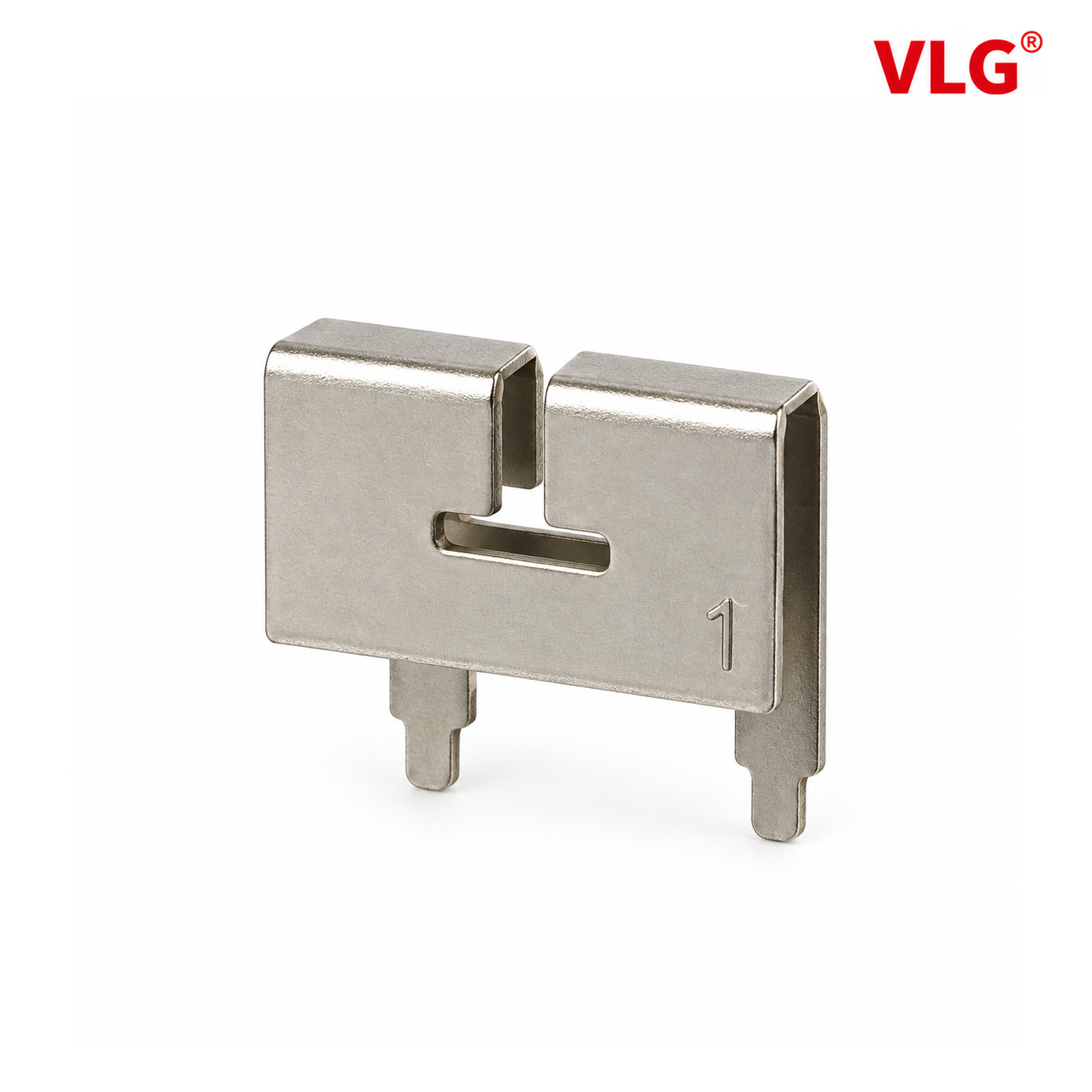
This article explains how to investigate those mechanisms using VLG V1350-152-A-01 as a stamped metal Wi-Fi antenna design example. It is a passive steel-sheet dipole specified for 2400–2500 MHz with an elastic-contact connection. Its documentation provides component data; the assembly scenario below is an engineering example, not a reported customer result.
Separate the three changes that assembly can introduce
| What changes | RF mechanism to investigate | Why it matters to the device user |
|---|---|---|
| The housing and nearby parts move into position | Conductive and dielectric loading changes impedance or the pattern | The finished product may behave differently from the open prototype |
| The antenna seats against its contacts | Connection geometry and impedance change | Assembly variation can become radio-link variation |
| The product takes its operating orientation | Directional and polarization response changes | A good bench link may not represent the intended use positions |
The aim is to identify which mechanism is limiting the link, then test a controlled correction. A better S11 trace alone is not proof of longer range, fewer dropped packets or higher throughput.
What folds and the T-shaped opening do in a compact antenna
The supplied drawing and product image show folded sheet metal, a T-shaped opening and contact tabs. The specification classifies V1350-152-A-01 as a dipole. It does not disclose a current-distribution simulation, equivalent circuit or the original design iterations.
At 2.45 GHz, free-space wavelength is approximately 122 mm, so a straight half-wave reference is about 61 mm. That is a scale reference, not a dimension to impose on this compact part. Three-dimensional geometry and coupling determine the actual RF response; the outside width alone is not the antenna's electrical length.
Folds and openings alter conductor geometry and local electric-field coupling. The T-shaped opening is therefore a possible tuning variable. It would be speculative to assign each side a separate resonant mode or draw a specific current route without an electromagnetic model or controlled prototype evidence.
To study the design, vary one approved slot or fold dimension while holding the board and assembly conditions fixed. Compare complex impedance, efficiency and patterns. A shifted resonance shows a matching change; improved radiated performance needs its own evidence. This connects the geometry to a testable design decision rather than treating its shape as a performance claim.
Why spring contacts need more than a DC continuity test
A continuity check establishes conductive contact at DC. At 2.4 GHz, the connection also has RF impedance. A simplified representation includes resistance and inductance along the connection and capacitance to nearby conductors. It is an analysis model, not an extracted circuit for this product.
As a labelled example, a hypothetical 0.5 nH series inductance has XL = 2πfL ≈ 7.7 Ω at 2.45 GHz. No 0.5 nH value is assigned to V1350-152-A-01. The calculation illustrates why a connection can pass a DC check and still change the RF match.
Contact displacement, seating and the surrounding geometry should be assessed with the mechanical tolerance stack. More compression is not automatically better. Obtain the allowed displacement, contact force and retention requirements from the approved design; do not infer them from a photograph. The electrical functions of the visible tabs also need the approved interface definition.
The intended benefit of controlling this interface is more repeatable electrical behaviour across assembly states and units. Demonstrate it through repeated assembly measurements before claiming an improvement in link consistency.
Impedance matching for the installed Wi-Fi antenna
The specification lists 50 Ω impedance and linear polarization. It documents 2400–2500 MHz operation, not 5 GHz or 6 GHz support. Confirm the radio's required bands before considering the mechanical integration.
Input impedance is complex: Z = R + jX. With a 50 Ω reference, Γ = (Z − 50)/(Z + 50). A matching network transforms the impedance presented at the radio interface. It cannot recover energy already dissipated in losses or remove a radiation null in a useful direction.
Use measured complex impedance to select a network, and calibrate or de-embed to the agreed reference plane. Control the test cable and fixture: if they interact with the radiator, moving them can change the apparent result. Evaluate the intended housing, board, nearby conductors and contact state together before freezing a tuning solution.
The source lists no waterproof rating for the antenna component. Protection of the complete device belongs to its enclosure and assembly qualification.
Use the V1350 data as a reference, not a finished-device guarantee
The supplied specification dated 2023-12-20 lists the following band-edge results:
| Frequency | VSWR | Gain | Efficiency |
|---|---|---|---|
| 2400 MHz | 1.23 | 0.09 dBi | 51.46% |
| 2500 MHz | 1.63 | 1.64 dBi | 50.42% |
Its full listed gain and efficiency table spans 2400–2500 MHz in 10 MHz steps. The reported gain range is 0.09–1.64 dBi, and efficiency is 50.42–52.93%. At 2450 MHz it lists 1.08 dBi and 52.28%.
Between the quoted band edges, gain increases by 1.55 dB while efficiency decreases by 1.04 percentage points. Gain and efficiency are therefore not interchangeable trends. Check their definitions, directional information and test setup before attributing the change to a specific physical cause. Likewise, “omnidirectional” does not mean equal gain in every three-dimensional direction.
These are historical source-document results, not fresh measurements or guarantees for a different host board. The two quoted VSWR points cannot replace a full sweep of the installed assembly.
Diagnose a lid-open versus lid-closed difference
Use the same board, radio settings, antenna and test link. Record assembly state before changing matching components. The following comparisons are proposed methods, not tests already performed for a customer.
| Observation | Possible contributor | Next controlled comparison |
|---|---|---|
| Resonance changes when the lid closes | Enclosure loading or a changed contact state | Separate the housing change from contact seating |
| RF response varies after reassembly | Seating or mechanical tolerance variation | Repeat assembly with recorded contact conditions |
| Match improves but communication does not | Pattern, polarization, interference or radio behaviour | Repeat OTA and link tests under the same conditions |
Change one factor at a time and retain the before-and-after configuration. For a geometry revision, keep the contact condition fixed. For a contact investigation, keep the housing and board arrangement fixed. This makes the result more useful than comparing unrelated prototypes.
Prove the benefit at the radio link
If a change improves useful received signal quality, the link may need fewer retries or may sustain a more useful data rate. The outcome depends on interference, receiver behaviour, traffic and the network. An RSSI increase alone cannot establish a range, latency or packet-delivery benefit.
Compare packet delivery, throughput and disconnect/reconnect behaviour using recorded channel, transmit settings, access-point position, device orientation and test traffic. Assess the closed product in its intended use positions. Report the RF change and the user-level outcome separately.
A result that reduces assembly-related link variation can matter to an equipment manufacturer even without a headline range increase. It may make the installed product more predictable. That remains a benefit to demonstrate through qualification, not a claim supplied by the antenna's component table.
Review embedded Wi-Fi antenna integration with VLG
Send VLG the radio model, required frequencies, PCB outline, antenna space, housing information and contact arrangement. Describe the symptom and assembly state, and include available RF and link measurements. Quote V1350-152-A-01 when requesting its current drawing and reference configuration.
Technical references: TI antenna selection and measurement guidance and TI matching and integration guidance. Their example geometry and component values are not specifications for V1350-152-A-01.
 +86 186 8871 1070


